March 31 is International Transgender Day of Visibility (Fig. 1). Please do something nice for your trans friends today (and everyday).
Figure 1. Photograph from a recent Trans Pride Parade to honor International Transgender Day of Visibility. Photo published here.
As for the title of today’s post, maybe it is the other way around? Last week, I was shut out from tweaking the calibration of the liquid crystals (discussed here) because the software glitch was still active. For that reason, I had only one session on the confocal. I imaged roots. Until now, I have been imaging mainly calibration fields and xylem. But roots are what I need to study so gaining experience with them seemed reasonable.
But when I had imaged roots, I had difficulty. The roots are round and lumpy; I struggled to capture an image that contains a goodly area of outer epidermal wall in face view. That is the area that I will measure; having plenty of wall to measure will reduce the total number of images. I decided to try osmotic flattening. After staining, I incubated the roots in 100 mM sorbitol for 30 min and also mounted the roots in the same. During incubation, thanks to osmosis (sister of Isis), water will flow out of the root, lowering turgor pressure; the decreased pressure will make the root sag, like a neglected bicycle tire.
I think the sorbitol worked. I imaged four roots mounted in water and another four (incubated and) mounted in 100 mM sorbitol. I wrote “I think” it worked because each root is different, wobbling and bending in its own precious way. Visually (I didn’t try to measure), the roots incubated in sorbitol had more outer epidermal cell wall area in focus. The increased area was modest, hardly a knock-it-out-of-the-park transformation; but the incubation is easy so I will add it to the protocol.
In imaging the roots, I noticed that sometimes the stained cell walls appeared faintly fibrillar (Fig. 2, left). These were wisps; not at all xylem spikes. When I checked the orientation calculated by the system for the fluorescent wisps (and surrounding cell wall), the alignment was not so bad (Fig. 2, right). The red lines, showing the alignment, are diverged from the direction of the wisps, but not by too much. The file of narrow cells (second from left) is an exception but those cells also seem a little out of focus.
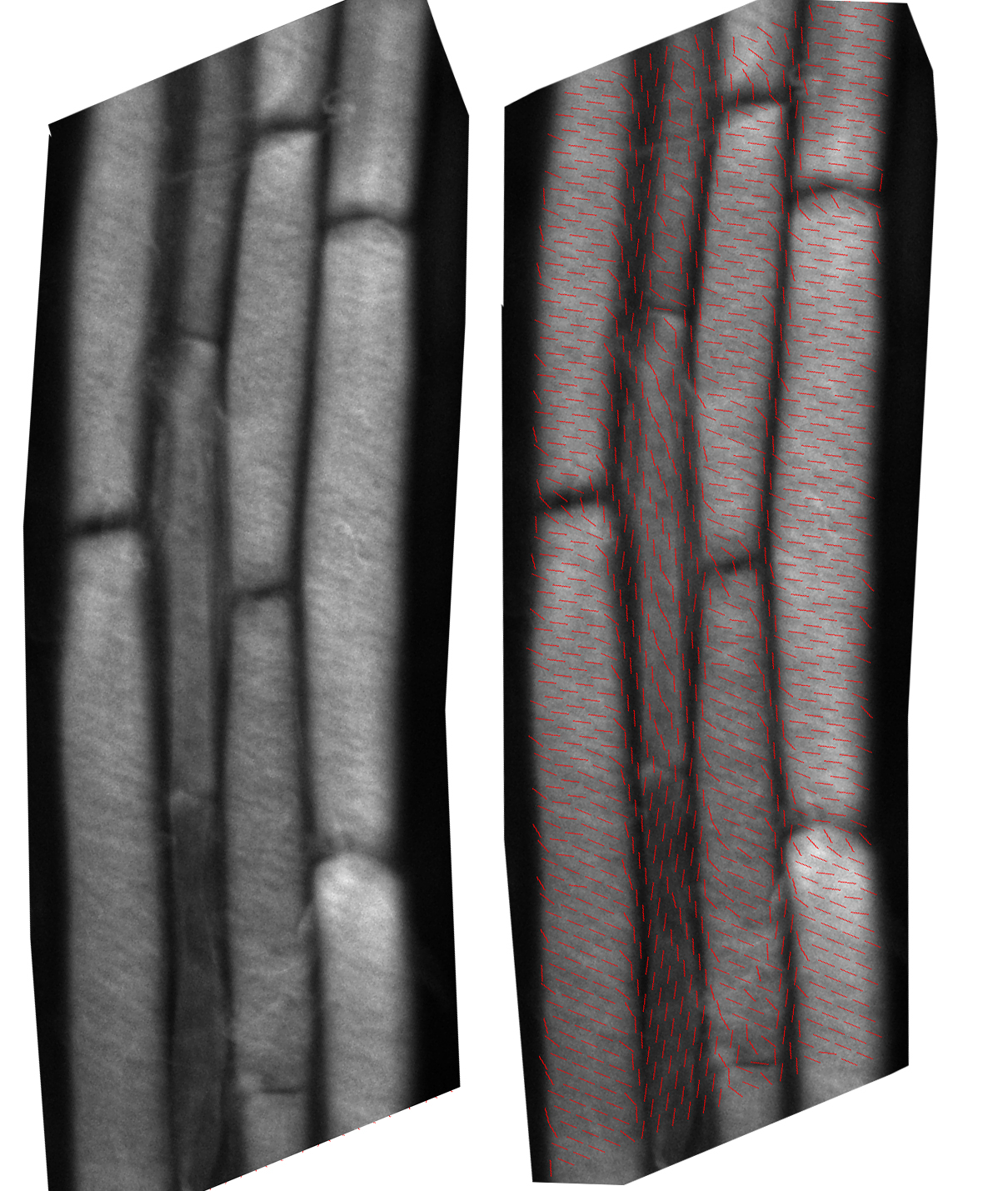
Figure 2. Living by my wisps. A arabidopsis root stained with fast scarlet and imaged on the confocal. Left: fluorescence excited by linearly polarized laser light. Right: The orientation for the fluorescence calculated by the Open Pol Scope system and represented by short red lines is overlaid on the fluorescence image. Note that the direction indicated by the lines is close to the direction of the fibrillar wisps present in many regions of cell wall.
Now, I mounted the roots on bog-standard microscope slides, not the dishes used for the rotation study I described last time, so I was not able to rotate the root and see if the discrepancy depended on the root’s orientation. But these fiber wisps were evident in roots running at various angles and the discrepancy was never larger than shown in Figure 2 and in some examples was maybe even non-existent. In fact the 10-ish degree discrepancy is about the same as the calibration error.
I am not sure why the roots seem to behaving more reliably than the xylem. Maybe, as Nat said in the comments on an earlier post, those ribs have a complex ultrastructure (winding rather than parallel cellulose) which could make the focal plane crucial. It would be interesting to take set of nice and narrow optical sections of some xylem ribs and see if the calculated orientation changes as a function of optical section depth. I could do this with roots too.
Deep breaths: With a better calibration and incorporating a background correction, I might be in business.
Nice!
It looks like the measure sort of falls apart at the anticlinal cell walls? Perhaps this explains some of the wonky results of the xylem, being tightly curled as they are. Unsure if PolScope produces this but the max/min intensity ratio might give a good indication of where this happens.
To speculate further, in anticlinal regions the flurophore is probably primarily oriented into the plane – but I would expect this just to introduce noise into the orentation measurement rather than reorient them to be primarily along the cell axis. Maybe the orientation in these regions becomes more sensitive of the tilt in your sample (top-to-bottom in this image)?
The anticlinal walls have almost zero fluorescence so any signal there is suspect. But in general we would expect the fluorescence to show up polarized parallel to the long axis of the wall (ie longitudinally for most of those walls) because unless the fiber is perfectly perendicular it will have a component projecting parallel to the wall.