Drink up! Whether you celebrate surrounded by dozens of your relatives or you let the day glide by quietly, I hope you are warm, fed, and happy. Alert readers will know that I missed posting last Sunday. I was traveling. Technically, I reached home late that afternoon but with respect to the travail part of travel, I was tired. So despite today being a holiday day and my hope that readers will be avoiding their screens in favor of conviving with friends and relations, I am posting.
Over the past weeks, some goings-on have been going on partly in my head: theoretical developments concerning to how to image the orientation of cellulose in the root. I have blogged about trials staining roots with fast scarlet (e.g., here and here). But I have said little about the trials over what comes next. To understand these, first I need to paint the backdrop.
Fast scarlet stains cellulose; but not only that, the fast scarlet molecules bind cellulose in an oriented manner. Oriented binding is not a surprise, cellulose itself is crystalline, a long narrow fiber made of chains of glucose lined up side-by-side. The binding site for the dye thus repeats again and again along the crystal, with the orientation able to change by no more than the structure of the crystal can change. Not by much.
For the epidermal cells of the root, I plan to detect the orientation of the dye molecules and thus learn the orientation of the cellulose. Dye molecules are far too tiny to image directly; instead, I will detect their orientation based on fluorescence polarization. In thinking about fluorescence (and absorption, which happens first), we rarely think about orientation. If you have measured an absorption spectrum, chances are you had a solution in a cuvette: molecules going in all directions all at once.
But absorption (of the kind that will lead to fluorescence1) follows the structure of the absorbing molecule. In particular, the molecule must have (or maybe, almost always has) a dipole moment. That means, the molecule is charged, in whole or in part. A dipole moment can be represented as line between the center of the positive charge and the center of the negative. Any single photon is polarized (polarization state—like wavelength, phase, and amplitude—is a fundamental property of a photon). When the polarization state is linear and parallel to the dipole, the photon has the best chance of being absorbed; by contrast, the chance is crap when the photon is polarized perpendicular to the dye’s dipole moment. The same goes for the photon emitted as fluorescence: the emitted photons is much more likely to be polarized parallel to the dipole moment2 than perpendicular (Figure 1).
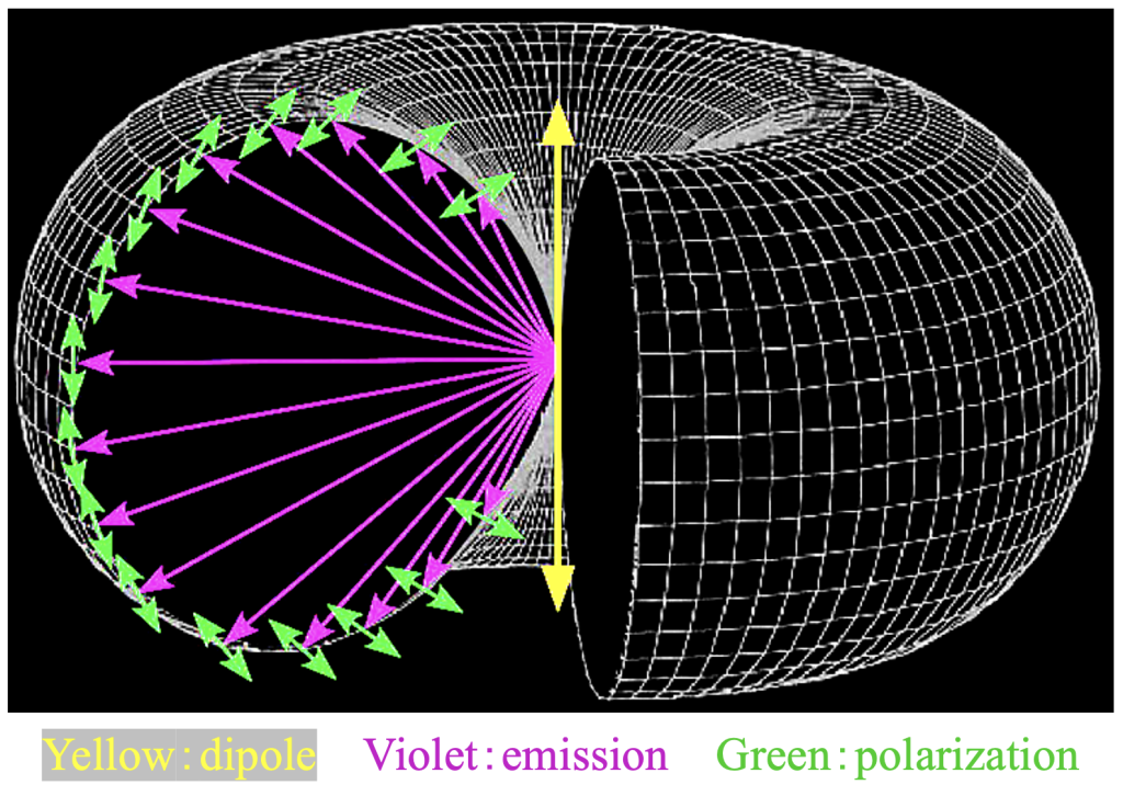
Figure 1. Schematic of probablity distribution of photons emitted by a molecule with the dipole moment shown by the central, double-headed yellow arrow. Not only is the intensity (violet arrows, represented by the donut radius) a function of position but so too is the polarization state (green arrows, represented by the white lines on the donut surface that run in the plane of the dipole moment. Figure courtesy of Tomomi Tani (AIST).
In other words, when a dye binds some component (cellulose, say) in an oriented manner, the fluorescence of the dye will be polarized. Detecting the degree of polarization and the net direction of the polarization is possible with various kinds of gear. One kind was developed by Rudolf Oldenbourg and collaborators at the Marine Biological Laboratory at Woods Hole Massachusetts. Their method is ingenious and works as follows.
Through a microscope, the sample is irradiated in steps with linearly polarized light of four different orientations (0, 45, 90, and 135º). A fluorescence image is collected for each. Actually, a fifth image at 0º is collected to account for any bleaching of the dye by the successive irradiations. For each pixel of the image, the four intensities are then used to calculate the degree of alignment among dye molecules and their net direction (Figure 2). Readers interested in learning more can read about it here.

Figure 2. BY-2 tissue culture cells stained with fast scarlet and imaged for polarized fluorescence. Images on the left (five panels) show fluorescence following excitation with light polarized linearly, roughly in the directions shown by the solid green line below each panel. Images on the right show the calculated azimuth and fluorescence anisotropy. Azimuth refers to the orientation of the dipole moment and is encoded by gray level (0º = white, 180º = black). The uniform gray intensity corresponds to the dipole moments being oriented roughly perpendicular to the long axis of the cell. The uniform gray of the background around the cell indicates residual fluorescence from an unknown source. Fluorescence anisotropy refers to the degree of orientation among the population of dye molecules, with the brighter the signal the greater the uniformity of orientation.
A key part of the Oldenboug system is the use of liquid crystals to generate the required polarization states. These crystals can be switched rapidly and efficiently by the computer; the settings used can also be adjusted to minimize problems from imperfections in the microscope optics. The gear mentioned above—and which I have brought to Birmingham—includes the liquid crystals on a slider, their electronic controller, and a software plug-in for Micromanager that drives the liquid crystal settings and image acquisition. That plug-in, named OpenPolScope, is available here.
With the background now sketched, I can relate how I have been trying to get the Oldenboug gear working here. I have to do two things: first, place the liquid crystal slider in the light path somewhere appropriate; and second, allow Micromanager (via OpenPolScope) to run the image acquisition. The latter is straightforward on wide-field microscope but such a configuration is suitable only for thin cells; for the thick arabidopsis root, I need to work with a confocal fluorescence microscope, otherwise out of focus light from deeper layers will compromise the signal. Actually this could be what is happening in Figure 2 because of out-of-focus light. However, confocal microscopes use lasers to excite fluorescence and have complex, proprietary systems of their own to run image acquisition.
Oldenbourg’s team worked out a way to integrate Micromanager and the software called Zen Black, used by confocals made by Zeiss. Happily, the imaging suite at the University of Birmingham’s Medical School has a Zeiss LSM780 confocal, the same model as at MBL. Generously, Rudolf lent me the liquid crystal slider that fits into this microscope. Thus, the first requirement (liquid crystal slider in the light path) is solved.
I expected a few humps getting the software integration ironed out. My expectations were borne out. At first, Micromanager could not find the liquid crystals. Thanks to Amit Verma, the amazing programmer behind OpenPolScope, Zooming in, we jumped that hurdle. But the next hurdle facing us is taller: the Zen Virtual Macro Editor. Turns out, this editor is required to integrate Micromanager and Zen. Annoyingly, when you pull down the “Macro” menu on Zen, there is a line “Virtual Macro Editor”, not grayed out; but in fact, the Editor is not installed. The menu just … expects installation? The imaging suite’s facility manager, Alex di Maio, is investigating how much Zeiss will charge for that extra bit—I predict the cost will be too much.
Necessity being the mother, father, brother, sister, and first cousin of invention, I have hoaked up a workaround. Even the better, the workaround would solve the problem of dodgy staining with fast scarlet. Mulling this over during the past few weeks, I have become excited. In fact, detailing the workaround was what I thought I would be the subject of this post. But having written this much to here, I’ll stop. I’ll save those details for next time. I might even have taken a step towards seeing whether this workaround might work at all.
1. For a molecule to be fluorescent, the absorption energy must be (mostly) retained in the molecule, rather than ebbing away as heat, and there must be an accessible pathway for the retained energy to be lost in a step, corresponding to the energy of a visible (or nearly) photon.
2. The dipole moment for fluorescence does not have to be in the same orientation as the one for absorption but in practice they turn out usually to be nearly the same.